
volt
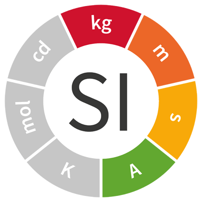
SI coherent derived unit with special name and symbol
| Name | Symbol | Quantity | Base units |
| volt | V | potential difference, electromotive force |
kg m2 s−3 A-1 |
 The volt, symbol V, is the SI coherent derived unit of electric potential, electric potential difference (voltage), and electromotive force. It is the special name for the kg m2 s−3 A-1. The volt, symbol V, is the SI coherent derived unit of electric potential, electric potential difference (voltage), and electromotive force. It is the special name for the kg m2 s−3 A-1.One volt is defined as the difference in electric potential between two points of a conducting wire when an electric current of one ampere dissipates one watt of power between those points. One volt is also equal to the potential difference between two parallel, infinite planes spaced one metre apart that create an electric field of one newton per coulomb. Additionally, one volt is the potential difference between two points that will impart one joule of energy per coulomb of charge that passes through it. |
|||
| Definition | h ΔνCs e-1 | ||
 |
 |
||
The volt is named after the Italian physicist Alessandro Volta (1745 – 1827).
Voltage
Voltage is the difference in electric potential between two points. An electric potential difference between two points can be caused by:
- electric charge,
- electric current through a magnetic field,
- time-varying magnetic fields,
- a combination of the above.
The difference in electric potential between two points in a static electric field is defined as the energy needed per unit of charge to move a test charge between the two points.

Using SI coherent units:
- V is the voltage across the conductor in volts, symbol V,
- E is the energy needed in joules, symbol J,
- Q is the charge in coulombs, symbol C.

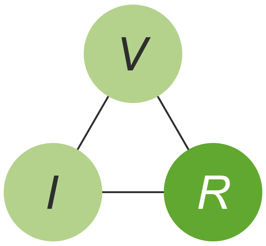
Ohm’s law
Ohm’s law states that the current through a conductor between two points is directly proportional to the voltage across the two points, with the proportionality constant being defined as the resistance of the conductor.
The relation between voltage, V, current, I and resistance, R can be represented mathematically by either of the following equations:
 |
 |
 |
Arranging the symbols V, I and R in the form of a triangle, provides a useful mnemonic for remembering the relation between these three quantities.
 |
 |
 |
The Josephson voltage standard
The Josephson voltage standard is based on one of two quantum effects predicted by British physicist Brian D. Josephson in 1962.
These Josephson effects occur if two superconductors are weakly coupled, e.g. by separating them with an insulating layer just a few nanometres thick. Exposure of this Josephson junction to microwaves creates voltage levels between the superconductors in exactly quantized steps.
These discrete voltage levels depend only on the ratio of the Planck constant, h, to the elementary charge, e, and the frequency, fJVS, of the microwaves. Each quantized step is generated at voltage VJVS, where:

Using SI coherent units:
- VJVS is the Josephson voltage between the two superconductors in volts, symbol V,
- N is the step number in integers,
- h is the Planck constant in joule seconds, symbol J s,
- e is the elementary charge in coulombs, symbol C,
- fJVS is the frequency of the microwaves in hertz, symbol Hz.
Using a typical microwave frequency of around 70 GHz, the interval between neighbouring steps is approximately 150 µV.
The quotient h⁄2e is also known as the magnetic flux quantum, Φ0, and can be expressed in webers.

For historical reasons, the Josephson constant, KJ, is used to represent the quotient 2e⁄h rather than its reciprocal value.

Using Josephson junctions, voltages can be reproduced with relative uncertainties of less than one part in ten billion. For this reason, the Josephson effect is used as the basis for constant reference voltages in national metrological institutes and in calibration laboratories of industry all over the world.
The quantum metrology triangle
The generation of standard voltages, using the Josephson effect, is one of three macroscopic quantum techniques that collectively form what is known as the quantum metrology triangle. The other two are the generation of standard resistors, using the quantum Hall effect, and the generation of standard electric currents using single electron pumps.
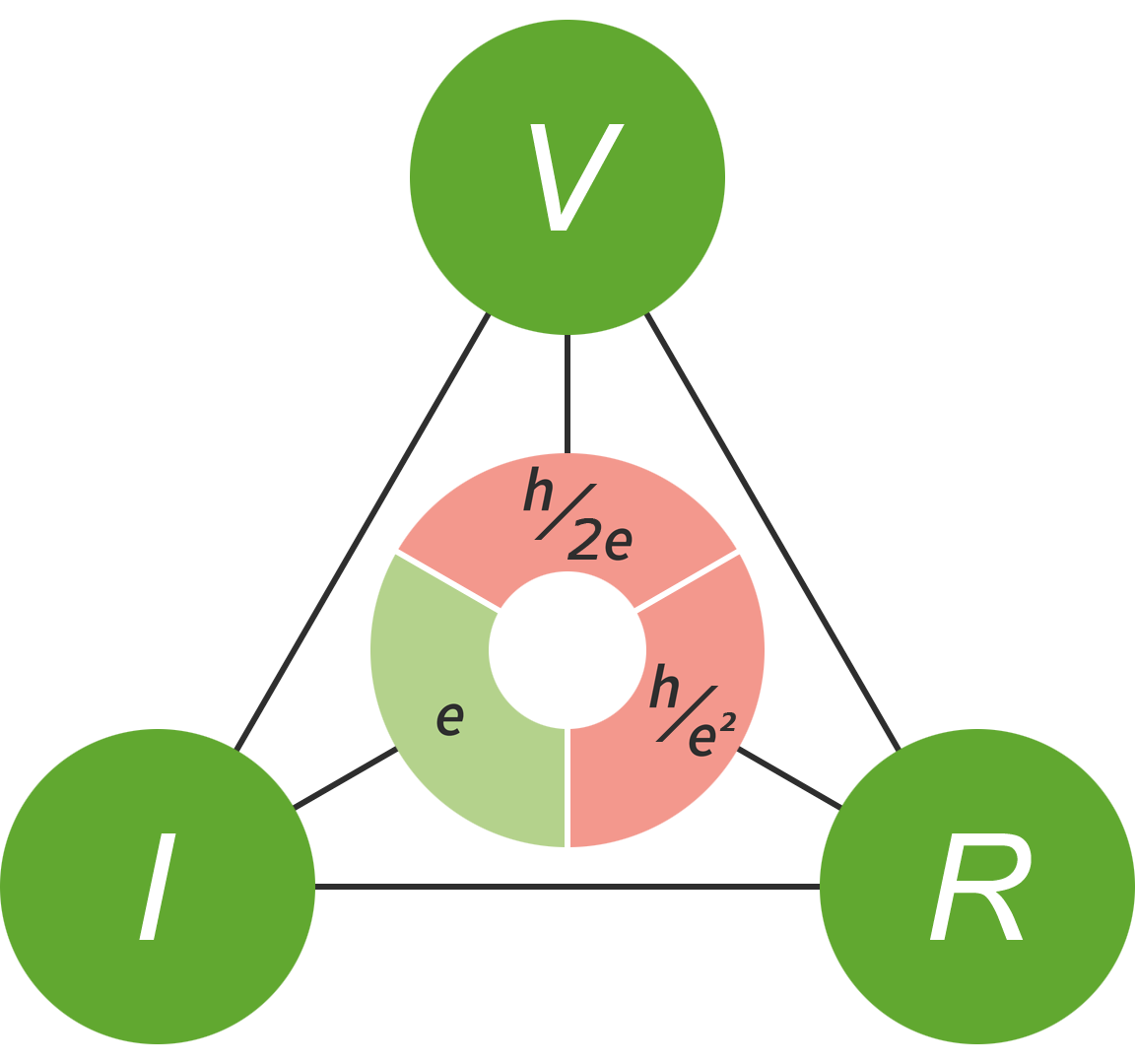 |
Measuring quantities at any two corners of the quantum metrology triangle allows the third quantity to be calculated to a high degree of precision via Ohm’s law:
 |
 |
 |
where:
- VJVS is a standard voltage generated using the Josephson effect,
- ISEP is a standard current generated using a single electron pump,
- RQHR is a standard electrical resistance generated using the quantum Hall effect.
The quantum metrology triangle relates three physical constants; the Josephson constant, KJ, the von Klitzing constant, RK, and the elementary charge, e.
Joule’s first law
Joule’s first law states that the power of heating generated by an electrical conductor is proportional to the product of its resistance and the square of the current passing through it:

Using SI coherent units, the proportionality constant is 1:

where:
- P is the rate of heat generation, or power, in watts, symbol W,
- I is the current passing through the conductor in amperes, symbol A,
- R is the resistance of the conductor in ohms, symbol Ω.
Substituting Ohm’s law gives:

Power transmission
Electrical power, generated in power stations, is distributed via transmission cables.
Using SI coherent units, the electric current passing through a power transmission cable is equal to the power transmitted divided by the transmission voltage:

where:
- I is the electric current in amperes, symbol A,
- Pt is the power transmitted in watts, symbol W,
- V is the transmission voltage in volts, symbol V.
From Joule’s first law, it can be seen that some power will always be lost when it is transmitted by electricity through a conductor of finite resistance. The power lost due to Joule heating can be calculated as a ratio of the original power:

where:
- Pw is the power lost due to Joule heating in watts, symbol W,
- Pt is the original generated power in watts, symbol W,
- I is the electric current in amperes, symbol A,
- R is the resistance of the transmission cable in ohms, symbol Ω.
For a given transmission power, the use of a higher voltage, and a lower current, leads to more efficient transmission of power.
For example, for a 25 Ω transmission cable, carrying 100 MW:
| Voltage in V | Current in A | Power loss in W | Power loss ratio |
| 250 000 | 400 | 4.0 × 10⁶ | 4.0 % |
| 200 000 | 500 | 6.25 × 10⁶ | 6.25 % |
| 125 000 | 800 | 1.6 × 10⁷ | 16.0 % |
| 100 000 | 1000 | 2.5 × 10⁷ | 25.0 % |
For this reason, power is often transmitted at hundreds of kilovolts, before being stepped down to 110 V – 230 V for domestic use.
Kirchhoff’s voltage law
Kirchhoff’s voltage law, also known as Kirchhoff’s second law, states that the directed sum of the potential differences, or voltages, around any closed loop is zero.
Measurement
A voltmeter can be used to measure the voltage, or potential difference, between two points in a system. A reference potential, such as the ground of the system, is commonly used as one of the two points.
